
Originally Published as: Anchoring Success: Foundation Attachment Systems for Cold-Formed Steel
Resources
For product selection and technical support on anchors, fasteners, and structural connectors for cold-formed steel and post-frame construction:
• Simpson Strong-Tie strong-tie.com – (800) 999-5099
• MiTek USA, Inc. mii.com – (800) 325-8075
• USP Structural Connectors uspconnectors.com – (800) 328-5934
• DEWALT / Powers Fasteners dewalt.com/anchors– fasteners – (800) 524-3244
• Hilti North America hilti.com – (800) 879-8000
The connection between a cold-formed steel building and the ground beneath it rarely gets the spotlight — but get it wrong, and nothing else about the structure matters.
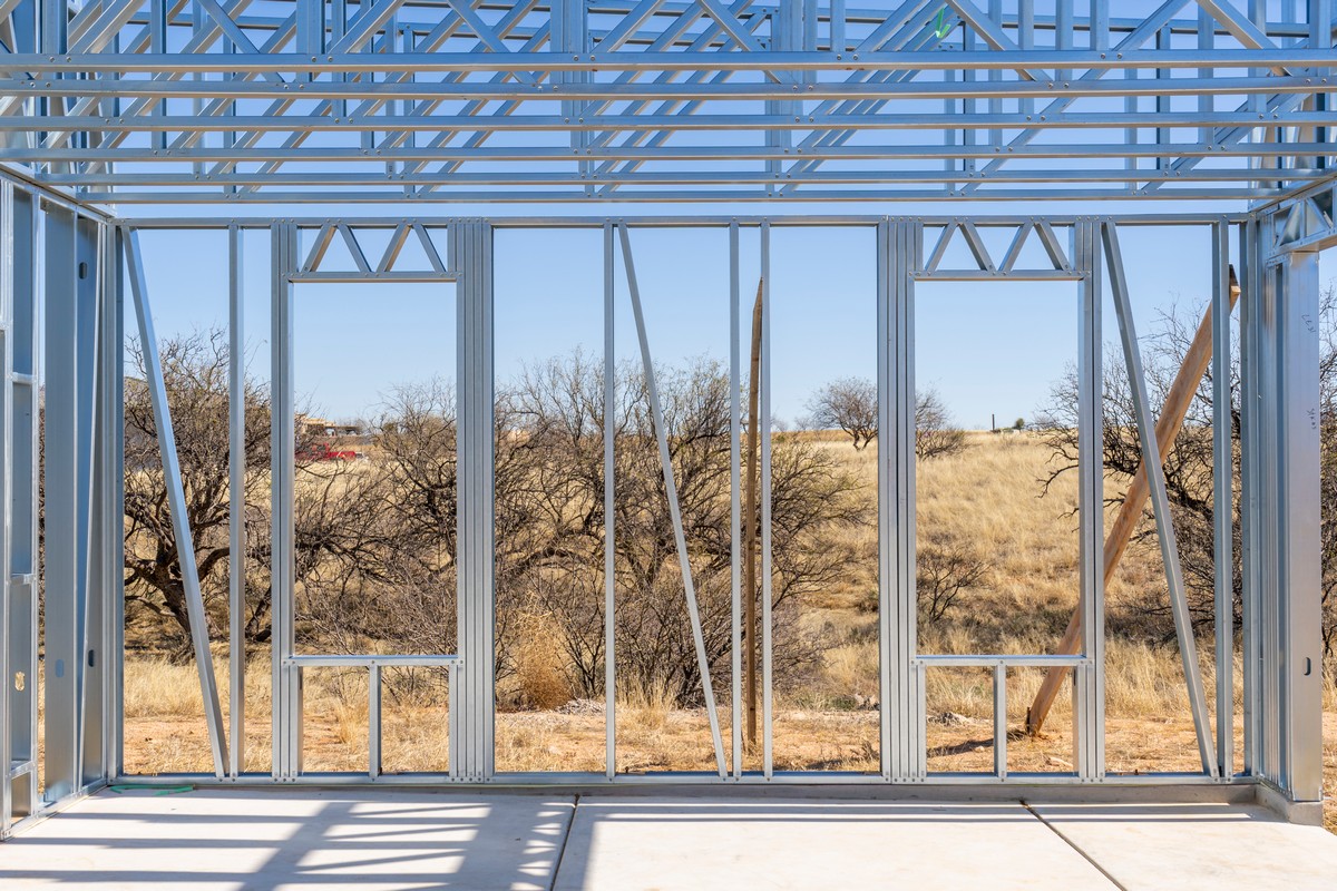
Cold-formed steel (CFS) has earned a permanent place in the metal building industry’s toolkit. Roll-formed studs, tracks, and trusses go up fast, resist rot and insects, and give engineers a predictable, code-recognized material to design around. But every advantage CFS offers above grade depends on a detail that’s easy to take for granted: how the building actually attaches to its foundation.
Foundation attachment is where load paths begin. Wind uplift on a roof, lateral shear from a windstorm, and the dead weight of the structure itself all have to travel down through the framing, through the bottom track, and into concrete, piers, or slab — without a weak link anywhere along the way. For builders and dealers working in cold-formed steel, understanding the attachment options — and when each one applies — is as important as understanding the framing itself.
Where the Load Path Starts
In a typical CFS wall or floor system, the bottom track is the first structural element to touch the foundation. According to the Association of the Wall and Ceiling Industry’s Cold-Formed Steel Framing Primer, first-floor framing can attach to a foundation or slab in several ways, and the right method depends on whether the connection is structural or non-structural. In non-structural applications, the bottom track is commonly fastened directly to a concrete slab with power-actuated fasteners (PAFs) shot through the track web, typically spaced 16 to 24 inches on center. Structural applications—where the connection must resist real uplift, shear, or lateral load—call for engineered solutions that can include power-actuated fasteners rated for structural use, expansion anchors, screw anchors, or epoxy and adhesive anchor systems set into cast-in-place concrete.
None of these methods is inherently “correct” on its own. The Cold-Formed Steel Engineers Institute (CFSEI) makes that point directly in its technical literature, noting that the decision on a fastening system should weigh structural capacity, the type of concrete being fastened to, installation conditions, and cost—not habit or convenience.
Matching the Anchor to the Concrete
Not all concrete is created equal, and that matters more than many builders realize. CFSEI Technical Note F502-18, “Attachment of Cold-Formed Steel (CFS) Framing to Precast, Post-Tensioned and Hollow-Core Concrete,” was developed specifically because standard anchorage assumptions don’t automatically transfer from a conventional cast-in-place slab to precast, post-tensioned, or hollow-core concrete components. The note walks engineers through anchorage options for each concrete type — including power-actuated fasteners, drop-in anchors, screw anchors, and expansion anchors — and provides worked design examples. So the selected anchor matches the substrate it’s going into.
For post-frame and metal building projects, that distinction shows up most often on slab-on-grade construction. Still, the same logic applies anywhere a builder is transitioning from steel framing to a concrete element the field crew didn’t pour and doesn’t fully know the history of. Post-tensioned slabs, in particular, carry embedded tendons that a poorly placed anchor can damage — another reason foundation plans, not field judgment alone, should govern anchor placement and depth.
Anchor Types at a Glance
Builders moving between wood, cold-formed steel, and traditional post-frame construction often work with several anchor families in the same week. Each has a different installation method, holding mechanism, and place in the load path. The table below is a general-purpose reference, not a design tool — actual capacity always depends on concrete strength, embedment, edge distance, and the manufacturer’s tested values for the specific product installed.
Codes and Standards Behind the Connection
Cold-formed steel design and its connections in North America are governed by standards developed by the American Iron and Steel Institute (AISI), most notably the AISI S100 Cold-Formed Steel Design Manual and the S200-series framing standards. AISI S240, the North American Standard for Cold-Formed Steel Structural Framing, addresses lateral design directly, including uplift anchorage requirements at the ends of shear walls. These exact connections keep a building’s walls tied to its foundation when wind loads try to lift or slide them. Builders specifying or installing foundation anchors on engineered CFS structures should expect their plans to reference these standards, and any substitution of anchor type or spacing should go back through the engineer of record rather than being decided on site.
Sizing, Spacing, and Embedment: What the Baseline Looks Like
Every jurisdiction and every engineered plan will set its own final numbers. Still, it helps to know the baseline that prescriptive residential and light-frame codes start from before wind, seismic, or engineered loading pushes those numbers up. Under the International Residential Code’s general sill-plate anchorage provisions, the commonly referenced minimums are a 1/2-inch-diameter anchor bolt embedded at least 7 inches into the concrete, spaced no more than 6 feet apart, with a bolt located within 12 inches of each end of every plate section and at least two bolts per plate. Those figures describe a baseline wood sill-plate condition — they are not a substitute for an engineered foundation plan on a post-frame or CFS structure, where uplift, shear, and bearing loads are typically higher and more concentrated than a prescriptive residential wall.
What carries over regardless of material is the logic behind the numbers: anchors work hardest at corners and plate ends, where uplift and shear concentrate, so those locations get anchors first and get checked twice. Concrete strength matters too — most residential-grade concrete falls in the 2,500 to 4,000 psi range, and anchor holding capacity is published against a specific compressive strength. Hence, an anchor rated for one mix isn’t automatically rated for another.
Note on prescriptive vs. engineered anchorage
Prescriptive spacing tables are a starting point for light, conventional construction. Once a structure is engineered — which is standard practice for most metal and post-frame commercial buildings — anchor type, diameter, embedment, and spacing are calculated from actual wind, seismic, and gravity loads and shown on the stamped plan. When the two disagree, the engineered plan governs.
Installation Practices That Protect the Connection
An anchor is only as good as its installation, and a handful of field habits separate a connection that performs from one that becomes a callback. Drilling accuracy matters most with post-installed anchors: holes drilled too close to a concrete edge risk breaking out the substrate on installation or under load, and manufacturers publish minimum edge-distance and hole-depth specifications for exactly this reason. Never force anchors into an undersized or misaligned hole to make up for a layout error.
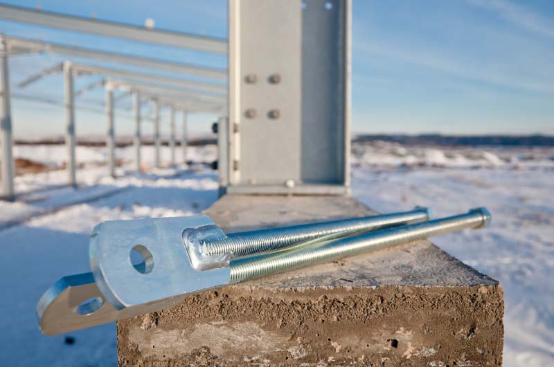
On cast-in-place bolts, a common and costly mistake is trimming a protruding bolt flush with the plate during framing. That extra thread length is there on purpose — it gives future retrofit hardware, hold-downs, or plate replacement somewhere to anchor. Once it’s cut off, that margin is gone for the life of the building.
Layout is easier to get right than to fix later. Wiring anchor bolts directly to the foundation’s rebar cage before the pour, or using a layout jig to hold spacing and plumb, keeps bolts positioned accurately through concrete placement and vibration of concrete —a much cheaper fix than drilling and epoxying a replacement anchor after the fact.
Drilling too close to a concrete or masonry edge is one of the most common installation errors — it risks breaking out the substrate and compromising the anchor’s holding power.
— Summary of field guidance, Journal of Light Construction, Anchors Field Guide
Corrosion Protection for Agricultural and Exposed Environments
Metal and post-frame buildings live in some of the harshest small-scale corrosion environments in construction — livestock confinement buildings, wash-down dairy parlors, fertilizer and chemical storage, and coastal or high-humidity regions all accelerate the breakdown of unprotected steel. Anchors and fasteners specified for these environments should carry coatings or base materials rated for the exposure, not simply the general mill-galvanized finish common on standard construction hardware. Hot-dip galvanizing to ASTM A153 is a common upgrade path for embedded and exposed anchor hardware, and stainless steel is worth the added cost in the most aggressive environments — direct manure or wash-down chemical contact, marine air, or applications where the anchor is effectively impossible to inspect or replace once the building is finished.
Corrosion at the foundation connection is particularly unforgiving because it’s often hidden — behind base trim, under a bottom track, or embedded in concrete — and by the time it shows visible symptoms, section loss may already be affecting capacity. Specifying the right material up front is far cheaper than diagnosing a hidden connection failure ten or fifteen years into a building’s life.
A Field Checklist: Common Mistakes Worth Avoiding
No anchor within 12 inches of a plate end. This is one of the most frequently cited inspection issues, and it’s exactly the spot where uplift and shear loads concentrate.
Cutting bolts flush “to clean up the look.” Leave the extra thread length for future hardware, inspection, or retrofit connections.
Substituting anchor type without checking the plan. A wedge anchor and an epoxy anchor are not interchangeable just because they fit the same hole diameter — their load ratings and appropriate applications differ.
Assuming all concrete is the same. Verify actual field conditions—slab thickness, age, and cracking—before choosing between anchor types, especially for retrofit or addition work tying into existing concrete.
Treating corrosion protection as optional. In agricultural and wash-down environments, the coating or base metal on an anchor is a structural decision, not a finish decision.
Practical Considerations for Metal and Post-Frame Builders
Pulling the previous sections together, a few field realities are worth keeping in mind on any project involving cold-formed steel and a concrete foundation:
Match the anchor to the load, not just the track. A fastener sized for wind uplift resistance is a different animal than one holding a non-load-bearing partition track in place, even though both may look similar in a box on the truck.
Corrosion resistance matters in agricultural and livestock buildings. Specify anchors and fasteners exposed to manure gases, wash-down chemicals, or high humidity with coatings or materials rated for that environment, not just general exterior use.
Know the concrete before you install the anchor. Cast-in-place, precast, post-tensioned, and hollow-core slabs each carry different anchorage requirements and different risks of hitting embedded reinforcement or tendons.
Follow the stamped plan. Once a foundation plan is engineered, anchor type, embedment depth, and spacing are part of that design—not a field decision.
Foundation attachment isn’t the part of a metal building that draws attention at a ribbon-cutting. But it’s the part doing the quiet, constant work of keeping everything above it exactly where it’s supposed to be — through the next windstorm, the next heavy snow load, and every ordinary day in between.
Sources
For product selection and technical support on anchors, fasteners, and structural connectors for cold-formed steel and post-frame construction:
- Cold-Formed Steel Engineers Institute (CFSEI). “Attachment of Cold-Formed Steel (CFS) Framing to Precast, Post-Tensioned and Hollow-Core Concrete,” Technical Note F502-18, developed by Derek Putz, P.E., Matsen Ford Design Associates, Inc. February 2018. buildusingsteel.org
- American Iron and Steel Institute (AISI). Cold-Formed Steel Design Manual and AISI S240, North American Standard for Cold-Formed Steel Structural Framing (Lateral Design). steel.org
- Association of the Wall and Ceiling Industry (AWCI). Cold-Formed Steel Framing Primer: A Guide to Understanding and Application. awci.org
- Steel Market Development Institute / Build Using Steel. buildusingsteel.org
- Journal of Light Construction (JLC). “Foundations: Code Requirements for Placing Anchor Bolts” and “Anchors Field Guide.” jlconline.com
- International Code Council. International Residential Code (IRC), Section R403.1.6, Foundation Anchorage. icc-es.org / iccsafe.org